The Shetland Attack Pony 6 (SAP6) Cave Surveying Device
Basic Use
SAP6 is operated by 2 buttons, A (nearer the laser) and B
Turn ON to take readings (this is measure mode): Press A twice in quick succession
Turn OFF: Press A twice in quick succession
Select a menu item: Press A
Move to next menu item: Press B
Return to main menu: cycle though menu items to
BACKoptionYou can always double click A to turn OFF and then start again (eg if you unintentionally go into calibration mode)
To charge the SAP6, unscrew the end cap and use a USB C cable. It takes approx 2 hours for a full charge. Do not charge the device from a powerbank whilst taking readings as this may cause interference with the magnetic readings
You can use the USB C cable to access files on the SAP6 and to update software for the SAP6 (details below)
Measure Mode (to take readings)
Press A to take a reading. You will get an error if the device is not already calibrated. You can choose either a short press of A (the reading is taken just after the button is released) or a long press of A (the reading is taken after about a second, or can trigger a countdown timer which can be configured). Play with each mode and see what suits you.
If the reading is successful you will see three numbers on the screen:
compass at the top (degrees or grad)
inclination (+ or - and degrees or grad)
distance (m or feet) at the bottom
If the reading fails you will hear an error double beep and see an error message. The laser will also flash rapidly several times.
In software version 1.6.0 and later the error messages are graphical:
Laser read error:
Magnetic anomaly:
Excess movement:

The laser stays on in measure mode. This does not require much power
Press B to cycle through previous readings. If you have enabled show extents, you will first see the horizontal and vertical extents of the current leg. You can tell which reading you are looking at by the small number at the right side of the display. Double click B to go back to the most recent reading.
If three successive readings are similar they are interpreted as a leg rather than a splay and the device will give a success beep (rising) and flash the laser twice. Similar means that, for each of the three pairwise comparisons between the three readings, the angular difference is less than 1.7 degrees and the change in distance is less than 5cm.
There is a bluetooth indicator on the top right of the screen:
 if connected,
  if not. If you lose the bluetooth connection, the device will store up to 20 readings in
the RAM memory. Readings are sent automatically when the bluetooth connection is restored.
if not. If you lose the bluetooth connection, the device will store up to 20 readings in
the RAM memory. Readings are sent automatically when the bluetooth connection is restored.
Readings can be saved to the flash drive to provide a backup. A reading taken more than 8 hours since the previous reading will be stored in a new trip file.
There is a battery level indicator on the bottom right of the screen. If you want to save power, turn off the device between stations.
Battery Life
Test results in ideal circumstances (room temperature, about 4m range to a white wall, 10 seconds between successive readings, display on):
~4500 readings taken
14 hours run time
There are some factors that affect battery consumption:
Temperature - poorer capacity with colder temperatures
Range - increased battery usage with longer legs
Cave colouration: increased battery usage with darker targets
Troubleshooting

LEDs
You may see some flashing LEDs at the position indicated.
Pattern |
Meaning |
|---|---|
Solid Green |
Device is charging |
Yellow (or red+green), 3 flashes |
Device is in safe mode |
Red, 2 flashes |
Device has crashed |
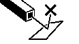
Hard Reset
Very occasionally the device will get a hard crash. The simplest thing to do is to perform a hard reset. The hard reset button is surface mounted on the PCB next to the USB socket. Use a toothpick to feel for this button on the PCB in the area indicated. You will need to press down rather than in (in the direction of the arrow on the image), and you should feel a definite click when you have found it. This will restart your device from safe mode and after a crash.
USB Drive not appearing
Occasionally you may get a condition where the device is unresponsive and it will not appear as a hard drive when connected to a laptop (or it repeatedly appears and disappears). In this situation it can be useful to deliberately enter safe mode. Safe mode is a special mode where the code on the device does not run, but the usb drive is available.To enter safe mode, press the reset button twice with about a 1 second gap. You should then see repeated yellow flashes x3.
You should now be able to connect it, update the firmware and possibly repair the filesystem - use fsck on Linux, or chkdsk on Windows.
Finally press the reset button one more time to go back to the normal mode.
Still having problems
If you are still having problems please email me. Include
the contents of error.log, calibration_data.json, and config.json if they are present
on the device.
Updating your software and hacking
Software updates
You can update the software on the SAP6 with newer versions downloaded from GitHub (https://github.com/furbrain/STIC/releases/latest). You can check the software version currently running on your SAP6 using the Info menu under Device.
To update your software, first connect the SAP6 to a computer - it will appear as a drive called SAP6. Next
download firmware.zip from the github repository, and extract all the files to the firmware directory on the
SAP6. Warning - all files should be replaced at the same time as there are various dependencies across the
files and the SAP6 may not work if only a single file is updated. Check that the device is working immediately after
updating.
Hacking
This is an open source project - feel free to make your own devices, make adaptations and improvements. All the hardware and software designs can be found on GitHub (https://github.com/furbrain/STIC).
SAP6 uses CircuitPython. All the code to run it is available on the device itself - just plug it into a laptop using a USB C cable and you’ll see a USB drive appear.
You can change the code as you see fit. The version of CircuitPython that comes with the SAP6 has several additional libraries built into it:
mag_cal: This contains all the maths needed for calibration
rm3100: This is a device driver for the RM3100 magnetometer
laser_egismos: This is a device driver for the laser module 2 by Egismos
caveble: This module is a cave survey specific module to talk to cave surveying apps such as SexyTopo
You can get this special version of CircuitPython from https://github.com/furbrain/SAP6_board/releases/download/1.0/sap6_cp_9.0.0.uf2
File layout
In the top level director of the USB Drive, you may see:
firmwareDirectory with the application code
fontsDirectory with the fonts used by the device
imagesDirectory with the images used by the device
readingsDirectory with any saved trips
boot.pyThe code that runs on startup, before all the other python code runs
code.pyThis code simply calls
runinfirmware/main.pyconfig.jsonThe calibration and settings data for the device
manual.pdfThis documentation
calibration_data.jsonA record of all the calibration shots you took the last time you tried to calibrate
error.logDebug info stored here if the device crashes or encounters an error
DEBUGIf this file is present, then the device is in debug mode. You can also use
debug.txt, or in fact any file withdebug(any capitalisation) as the basename. You won’t see the normal battery charging screen, but you can double click A and start the main device running. You also get a serial connection on/dev/ttyACM0or/dev/ttyUSB0on linux orCOM1on windows, which will show debug information.
Make Your Own
You can build your own SAP6! You will need access to a 3d printer and ideally a laser cutter. You will also need to make some PCBs - you can etch these yourself or get a company to do it. Seeed and JLCPCB are some of the many companies that can do this for you.
PCB
Get the gerbers from
GitHub (https://github.com/furbrain/STIC/releases/latest):
download pcb.zip. That will contain the gerbers for the main board and also the button board. The traces are all
pretty wide so you can mill or etch the board yourself.
See the bom.csv in pcb.zip for the list of components and where to get them
Solder the components onto the board - they are all fairly chunky so you don’t need to be a whizz at soldering. Don’t solder the display on initially, this is easier to do while attaching the board to the mount. Note the button 3-pin connector goes on the bottom of the board.
Plastic parts
From GitHub (https://github.com/furbrain/STIC/releases/latest)
download hardware.zip
You will need to 3d print the following STLs:
abs\shell.stlabs\cap.stlabs\bezel.stlabs\shim.stlabs\mount.stl
The bezel and cap may be best printed upside down. You may find it easier to print the cap_with_vanes - this
has some very thin tabs to help support it as it is being printed which can then be removed. Once printed, use a
soldering iron to push 4 brass M3 inserts into the holes on the end of the shell. You will also need to push one into
the hole in the mount.
TPU parts
Print tpu\Boot.stl in the softest TPU you can get away with.
Acrylic parts
Ideally, you should laser cut the following DXFs from 3mm clear acrylic. However, the designs are fairly simple so you may well be able to cut these by hand
acrylic\End plate.dxfacrylic\Window.dxf
Gaskets
Rubber\Cap Washer.dxfRubber\Refined Gasket.dxf
You can use 1mm silicone sheet or EVA foam for these pieces. Note that EVA foam works well but permanently deforms when used so will need replacing if you ever disassemble the device. Alternatively, generous use of silicone grease can mean you don’t need these parts at all.
Making the sled
First solder everything apart from the display onto both PCBs. Note you can either use a mini-SPOX connector or JST PH-2.0 connector for the battery. Check it is the right way round for your battery connector. Attaching the battery reversed may cause permanent damage.
Put the display in it’s location on the mount and put the main pcb on top.
Screw the PCB in place using a brass M3 screw, and solder the display in place.
Attach the cable to the laser module and the PCB.
Screw the laser module in place using M2 or #2 brass screws.
Attach your battery to the board, but don’t glue it in place just yet.
Installing software
You will first need a copy of my version of CircuitPython, which comes bundled with a few extra modules to save space, you can download it from https://github.com/furbrain/SAP6_board/releases/download/1.0/sap6_cp_9.0.0.uf2. The extra modules are listed in Hacking
You also need to put the device in bootloader mode: press the reset button twice in quick succession and plug into your computer - it should show up as a drive called “XIAO_SENSE”
Linux
If you have access to a linux computer, then there is a script in firmware\installer called installer.py:
usage: installer.py [-h] [-f] [-t] [-c] [-hw HW_VERSION] [-d] [-l]

Installer for the SAP6

optional arguments:
  -h, --help            show this help message and exit
  -f, --skip-firmware   Do not try to update the CircuitPython Firmware
  -t, --skip-tests      Skip the testing section - just install the code
  -c, --skip-code       Skip the code installation
  -hw HW_VERSION, --hw-version HW_VERSION
                        Specify the hardware version, set to 0 to skip
  -d, --debug           Place a DEBUG file in the root directory, putting
                        device in debug mode
  -l, --calibration     Place a calibration file in the root
                        directory,allowing to perform a (incorrect)
                        calibration
Copy the Circuitpython inyo the installer directory and call it firmware.uf2
Next run the script without any arguments; it will find the device, install the CircuitPython firmware, and then take you through a testing procedure for the board - it will check that everything is working; you will need to press button A, you should hear two beeps of different tones, then the display will ask you to press button B.
It will then install the rest of the code and you should be up and running
Windows
Installation instructions not done yet…
Final Assembly
You can see a video of this process at https://www.youtube.com/watch?v=XkpvDELlksQ.
Attach the cable to the connector on the PCB
Apply some silicone grease to the bottom of the boot and place on the button PCB. Make sure that A is at the end opposite where the cable comes out
Apply some silicone grease to the “shelf” on the boot
Push the boot and PCB into the shell. Make sure A is nearest the end. The cable should be pointing into the shell
Push the shim into the shell - it should hold it firmly in place. You may need to press the shell down against a hard surface
If you have used a mini-SPOX connector for the battery, bend it about 45 degrees towards the laser
Put a blob of glue on top of the laser and put the battery on it. This step is not in the video
Connect the cable from the button to the main PCB
Push the sled into the shell, keeping the button cable out of the way
The side tabs on the sled should mate into some dents in the inner wall of the shell
Smear some silicone grease on the end of the shell, then put the gasket on
Put more grease on the gasket, and put the acrylic end plate on, and screw into place with brass M3 screws.
Put a little grease in the channel in the base of the cap, and put the cap washer in, then a little more grease on the washer
Screw the cap on - and you’re done.
You will next need to calibrate the device before you use it. If you are successful in building your own, please let me know, especially if you have any suggestions to make for this guide.
Make A Derivative
Want to use different hardware? Planning to use different sensors or displays - or even processors? Here’s how to adapt the code to include your own hardware. You will need to be comfortable with enclosure design, PCB design and CircuitPython programming. This section covers the changes you will need to make to the code.
Select a hardware version
Please select a number greater than 20 as the main version number for your series of ponies! This allows me to make my own increments and keep my major version numbers sensible.
Creating a new hardware class
This is only needed if you have changed the sensors or display. You will need to create a new file in the versions
directory - you can name this what you want. It should contain a class called Hardware that subclasses
HardwareBase from hardware.py. It should override all the methods marked as @abstractmethod, and should have all the members
described. Note that Magnetometer and Accelerometer classes should have properties acceleration and
magnetic respectively: see
https://docs.circuitpython.org/en/latest/docs/design_guide.html#sensor-properties-and-units. This
means that most of the CircuitPython sensor drivers for accelerometers and magnetometers will
“just work” if you create an instance of them.
See versions\hardware_v1.py for an example of how to implement this. Note the __init__ function takes a pins
parameter - this allows you to have different versions of your setup with different PCB layouts without needing to keep
updating the hardware class. You can create a new Pins class in pins.py
Creating a new display class
versions\display128x64.py is a display implementation for a 128x64 display. If you wish to use a different size
display you will need to subclass DisplayBase from display.py - again you will need to override all the
@abstractmethod functions. You will then need to ensure your Hardware class returns an instance of this class
when create_display() is called.
Creating a new layout
Once these two steps are complete, you will need to create a Layout - this represents a specific physical
implementation of the device. For example, there are two versions of the SAP6, the second (v6.2) is slightly shorter
so it will fit into a Peli Micro case. You can see that there are two different layouts in layout.py - one has a
slightly shorter laser offset. This could allow you to create a different enclosure, even have the PCB at right angles
to how it normally is, and just add a new layout file without needing to change anything else.
Start by creating a new Layout with the same mag and grav axes and laser_offset. Set the pins entry to the name of your
Pins class, and the hardware entry to the name of your hardware file.
In version.py add an entry to the LAYOUTS dict, with the version numbers for your layout.
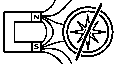
Working out correct values for axes and laser_offset
You need to tell the pony which way round its magnetic and gravitational sensors are. With the laser pointing away from
you and the display upwards, the X axis is positive to your right, the Y axis is positive away from you (along the laser
beam) and the Z axis is upwards. You can use Settings->Info->Raw Data to visualise the raw output of the
magnetometer and accelerometer. You specify the orientation as follows (taken from CircuitPython_mag_cal documentation):
For each axis XYZ of your device, state the corresponding axis of your sensor. Add a + or - in front to let us know if it is inverted. So for a sensor that is correctly mounted it will be “+X+Y+Z”. If the sensors Y axis points to the left of the device, the X is forwards and Z is down, specify this as “-Y+X-Z”
To determine the value for laser_offset, run the laser calibration procedure, then check config.json for
the value to use as a default.
Telling the pony what it is
You need to put the hardware version in the pony’s non-volatile memory - this is stored even when turned off and is not affected if the filesystem is wiped. To set the hardware version, access the serial console and enter the following:
import microcontroller
microcontroller.nvm[-3:] = bytearray((XX,YY,ZZ))
where XX, YY, ZZ are your version numbers
When it’s all done and working, create a pull request and I will merge it into the main repo.
Why not just fork the repo and overwrite the hardware code?
Well you could! This is open source after all. However, by going through the steps above means that you can continue to benefit from any updates to the main SAP6 codebase - you can just download and copy over new versions of the firmware and everything should just work.